Welcome to stockholmviews.com
September 1, 2024
Range rover P38a EAS pressure switch of vehicle test rig
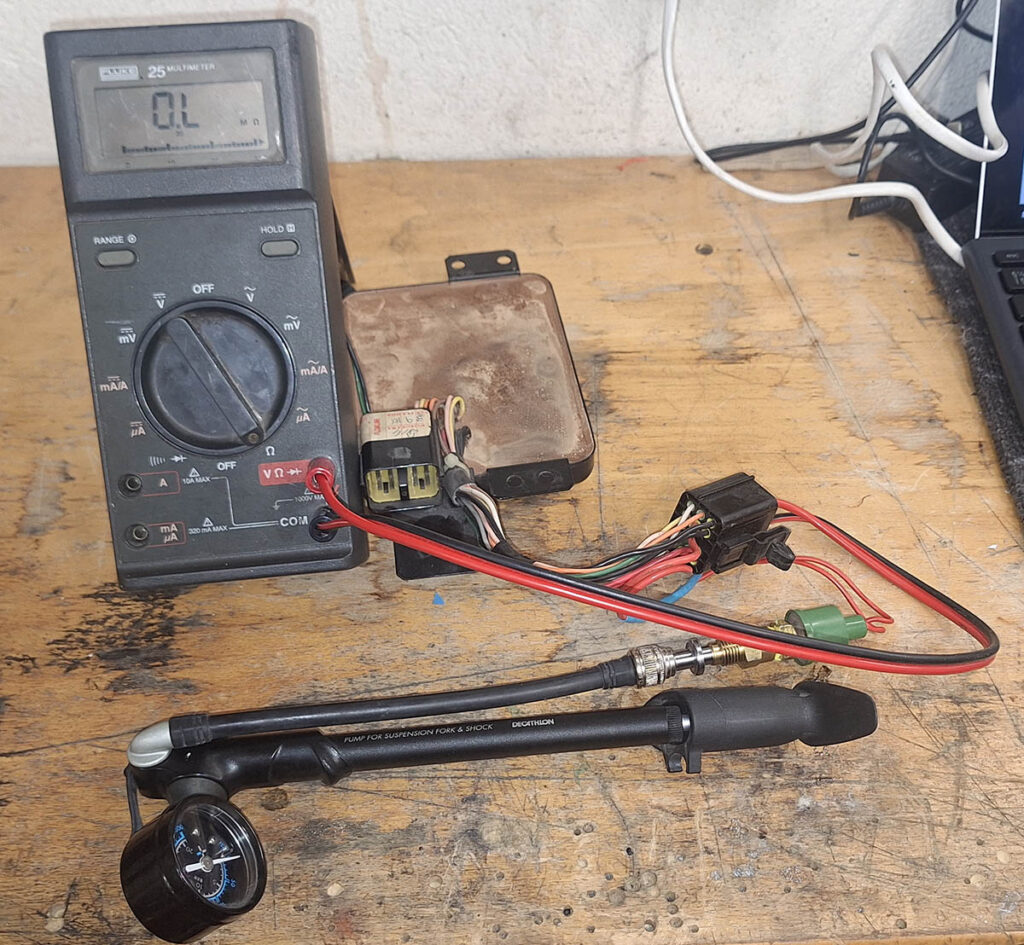
Since I’m hunting EAS issues I came up with this simple off vehickle tester for P38 EAS pressure switch.
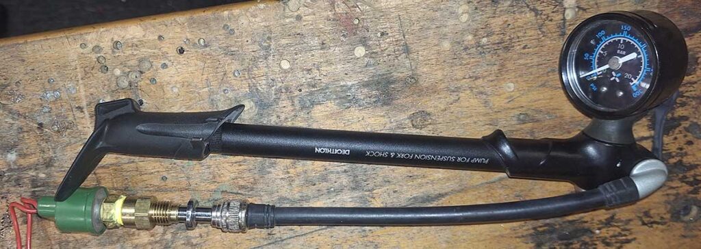
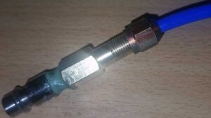
What you need is an mountain bike Suspention air pump and an adapter NPT to Schrader valve
I used what I had in my box and came up with what yo see in the pictures but if I would have started from scratch I had bought a NPT-NPT adapter and a shrader with the same thred.
You also need a test device like a multimeter or even better a bulb and a power source (Since it put some load on the pressure switch cointacts).This is how it looks, nothing fancy quite straigt forward.
Demo of funktional test of Range Rover P38 EAS (Electronic Air Suspension) pressure switch.
Simple testrig using a hand pump that are quite common as used for MTB suspension, this sample is capable of 300psi so more than enough for this task. Test connectors can be whatever you find suitable, it’s only 2 wires that are neded and yoy gan easily trace them by eye, i used some narrow generic flat contacts comonly used on …. most thisngs in old vihecles :D
Pump andad apter connected to pressureswitch switch should be closed at about 150psi and open arround 110 (Not super critical).
I happened to have a schrader valve tap to I improviced this adapter Link to parts ;)August 25, 2024
Range Rover P38a EAS Valve block test box
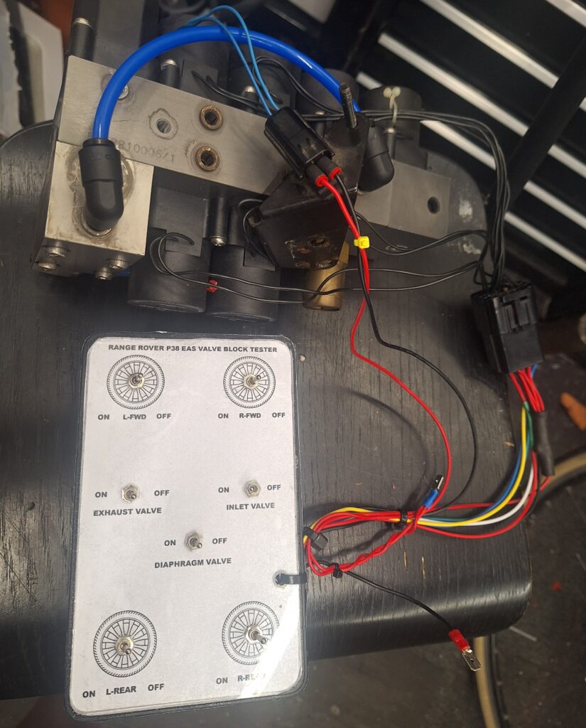
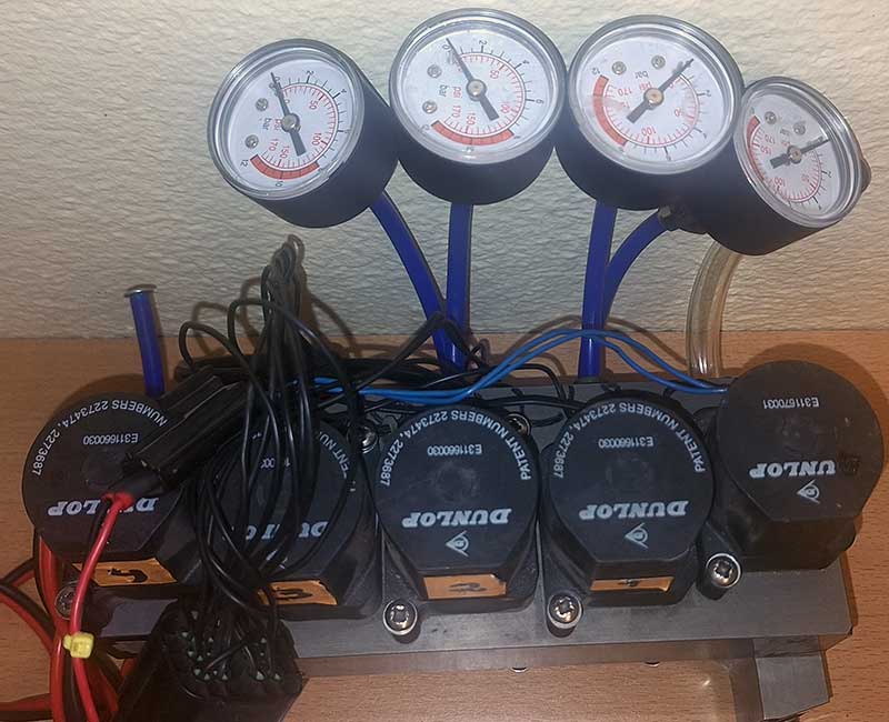
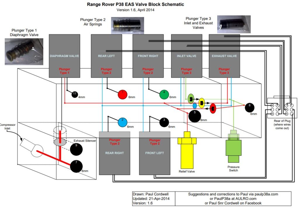
Due to my wish to be able to test a EAS valve block off vehickle I decided to build myself a test box. This will make it easy to check the valve block for leakage before taking a decission to rebuild it and also for primary evaluation after a rebuild.
The box is quite straight forward to build and you can chose to use any kind of togle switches.
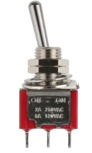
I went for smal 6A lever type switches as they make a god indication of if they are on or off, if you like to be fancy it is aways possible to use switches with indicator lights.
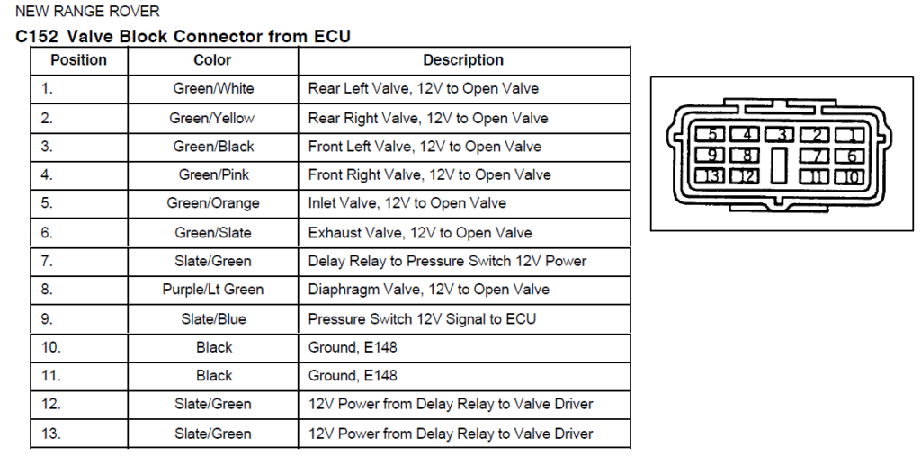
I had a small box from an old wifi router that I used to hold the switches and wired it up to a connector to fit the valve pack (You either get one from an old valve pack driver or boy one from for example digikey. I simply wired +12V to center pin of all switches in the test box then a ground lead (-12V) to pin 10 and 11 of the test connector. Then simply wire the corresponding switch to the test plug pins 1-6 + 8 I left the others unconnected.
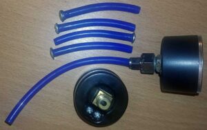
I also made an adapter so that I can use a small shop compressor to test the valve block off-car and bought a bunch of cheap manometers to be able to check for leaks over a period of time.
To be able to do a leak check of the valve pack it is not nessesary to hook-up a air reservoir (just plug port 6) or dryer (Use a jumper tube between port 5 and 7) and you can also omit the pressure switch and replace it with a plug or manometer.
I power it all with a 12V 50A Switched power supply bought at Amazon (Frequently used on 3D printers). This PSU also have enough power to be used for EAS Compressor testing and breaking them in gently.
The test box: Blu jumper hose is replacing the air dryer during valve block bench testing.
The loose flat contacts are for 12V power source.
the small black connector with the blue leads are for the diaphragm valve and are connected with standard 2.8mm insulated crimpcontacts.
Valves doesn’t care about polarity during testing.
Note: Valve block driver and pressure switch is not used in this rig and need to be tested in other way if required.
Left: Adapter for shop air compressore pressure to valve block, my compressor does not reach 150psi (I use 6-8bar) for leak check that is god enough since a low pressure actually reveal leaks in a better or at least as god vay as high pressure.
BOM:
Switches used by me:DigiKey P/N 2449-ANT11SECQE-NDConnector parts:
PART: 344260-1-ND
MFG : TE Connectivity AMP Connectors / 344260-1
DESC: CONN RCPT HSG 13POS BLACKPART: 344261-1-ND
MFG : TE Connectivity AMP Connectors / 344261-1
DESC: CONN TAB ANTI-BACKOUT 13POS YELPART: 17-345809-1CT-ND
MFG : TE Connectivity AMP Connectors (VA) / 345809-1
DESC: CONNTACT TAB 20AWG CRIMP TIN
- Suitable Powersupply Car battery or: Switched Power supply
- A bunch of manometers are usefull for leak check of the valve pack.
Get some here: Manometers 1/8″ fitting- And some pneumatic tube adaptors for the manometers.
NTP 1/8″ female to 6mm pneumatic tube
Link to larger valve block image + more : PaulP38A.com
Test panel template: ON=Solenoid energized
July 4, 2024
PCB UV exposure box from flatbed scanner
Disclaimer not yet officially published and will be updated frequently!
I wanted to be able to make my own prototype PCB’s and was consider many different methods.
My conclution is that part from the not so nice to handle liquids that is nessesary to use the photoresist and etching method is by far the best and fastest for a home shop. This is tep one in a small series that will cover the tools and methods that I have ben choosen. Hopefully I will also build a PCB drilling CNC ;)
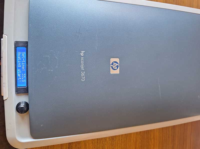
The victim to become transformation to UV exposure box a HP Scanjet 3670 bought for 20 euro’s.
It has been striped for all its internals I just keept the frot push buttons and two of them are used for start/stop of timer. It hade a space at the front top where I was able to cut a hole ad squeeze in the LCD.
I 3D printed a bezel for the LCD as my cutting wasn’t to pretty , and the potento meter knob was also printed files included att the bottom ;)
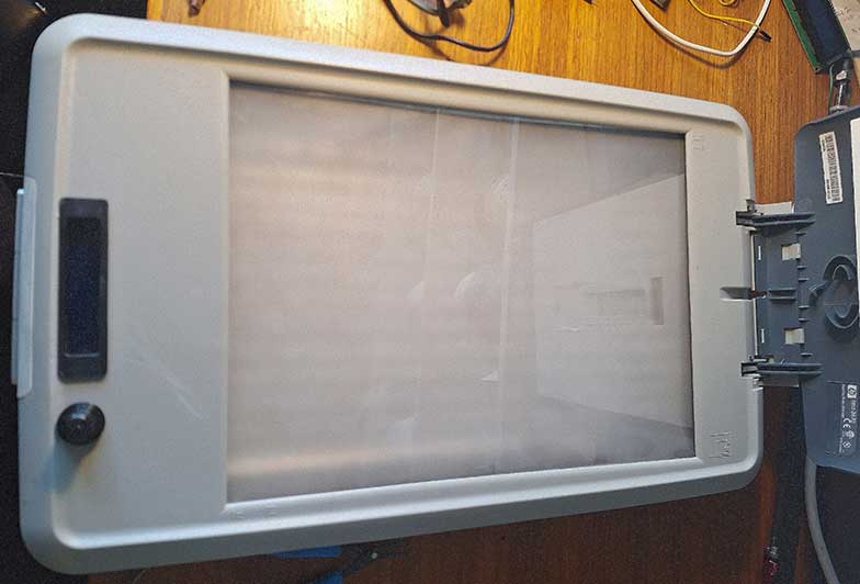
A pic showing the diffusion film being taped under side of and arround the edges of the scanner glasssurface. The LED strip was first mounted on a white cardboard that was mounted with hot glue to the botom of the emty scanner casing. I was cutting the whole 5 meter UV light strip in short lengths and then soldered jumper wites between them. Later I found a much better and easier method, simply folding the strip!
Hardware and build for PCB UV exposure box.
Old flatbed scanner (Pick one with enough space for LCD, PCB boards and Potentiometer BOM below.
BOM: LED+BOX MOD
UV Led strip 5 meter.
White hard or cardboard.
Diffusion gel film.
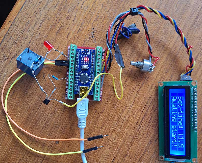
The timer circuit and code.
No flickering solution is based on this code: devxplained.eu/en/blog/using-lcds
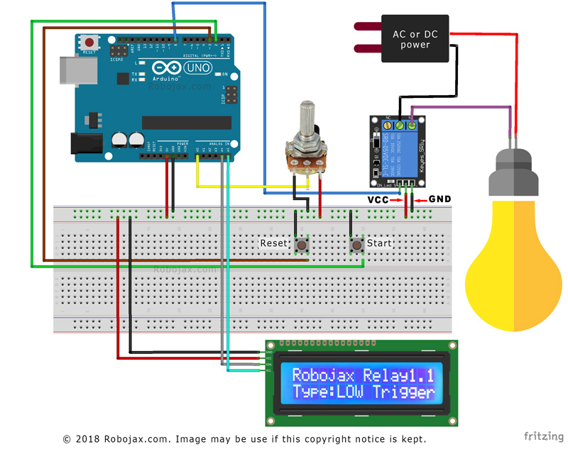
Timer code partly borrowed from: robojax.com
Schematics also by robojax.com my PCB does however carry all components exept LCD potentometer and buttons this will make it more easy to place the parts inside the scanner itself ther for I also used a Arduino Nano instead of UNO .
Schematic fritzing style!
And my rats nest for testing. The UV box that I’m using right now has this circuit and is point to point wired with soldered jumpers, everything held in place by some fancy hot glue haha….
Display and arduino +relay is also powered with the same 12V power supply that are used for the UV led strips by the use of a 12v-5v DC-DC buck converter.
- BOM: TIMER ELECTRONICS
- 10K Multi turn poteniometer
- Arduino nano
- Relay board or relay + transistor
- Display HD44780 i2c
- 12V to 5V DCDC converter
- Wires, soldering equipment + time and patience
The full code for UV exposure timer used in Arduino IDE (zip download near bottom of this page)
//By tinker site https://stockholmviews.com//Most of the code “by https://robojax.com/” A few modifications to suite my needs for a PCB UV exposure board.//I also finally managed to get the i2c display code to become flicker free.. eureka! ;)
// start of settings for HD44780 with I2C#include <Arduino.h>#include <LiquidCrystal_I2C.h>#include <IoAbstractionWire.h>#include<Wire.h>// Set the LCD address to 0x27 for a 16 chars and 2 line displayLiquidCrystal_I2C lcd(0x27, 16, 2);
#define relayPin 8 // the pin relay is connected#define potPin A0 // the pin potentiometer is connected#define resetPin 3 // the pin where rest switch is connected#define startPin 2 // the pin where start switch is connected
#define relayType ‘L’ // Relay trigger type. L for low and H for highconst int maxTime = 200;// maximum timer time in seconds 2 minutes is more than enough for my PCB UV boxconst int minTime = 2; // miniimum timer time in seconds
// do not change anything bellow herelong duration;// holds the duration of timerint potValue;// holds the variable resistor (potentiometer) valuelong rememTime;// holds current run timeint relayState =0;// holds relay state
void setup() {
lcd.begin(16, 2);lcd.backlight();lcdDisplay(0, “Set-time:”, ” ” , “.S” );lcdDisplay(1, “Awating start! “, 0, ” “);
Wire.begin();pinMode(relayPin, OUTPUT);pinMode(resetPin, INPUT_PULLUP);pinMode(startPin, INPUT_PULLUP);attachInterrupt(digitalPinToInterrupt(resetPin), reset, LOW);
Serial.begin(115200);// initialize serial monitor with 9600 or your choice of baud rate.if(relayType == ‘H’) // H or L depending on activted LOW or activeted HIGH by pin 8.{digitalWrite(relayPin, HIGH);// turn the relay OFF and keep it OFF.Serial.println(“Countdown relay”);Serial.println(“Type:LOW Trigger”);}else{digitalWrite(relayPin, LOW);// turn the relay OFF and keep it OFF.Serial.println(“Countdown relay”);Serial.println(“Type:HIGH Trigger”);}delay(0);}
void loop() {potValue = analogRead(potPin)/10;// reads the value of the potentiometer I use 10K multi turn pot (value between 0 and 1023).
int durationCalc = map(potValue, 0, 102, minTime, maxTime);// convert A0 value to time set minTime and maxTime.if(digitalRead(startPin) ==LOW){duration = durationCalc;rememTime = millis()/1000;relayState = 1;controlRelay();// turns the relay ON}if( ( millis()/1000- rememTime) > duration ){relayState = 0;// change relay state to OFFcontrolRelay();// control relay with new relay state}Serial.print(“Time set: “);Serial.print(duration);Serial.print (” S “);if(relayState ==1){
lcd.noBlink();lcdDisplay(0, “Run-time: “, duration, “.S”);lcdDisplay(1, “Exposing: “, getRtime(), “.S “);Serial.print(” remain: “);Serial.print(getRtime());//Serial.print(” .S”);}else{lcd.noBlink();lcdDisplay(0, “Set-time: “, durationCalc, “.S”);lcdDisplay(1, “Awating start! “, 0, “”);}Serial.println();delay(50); // wait for 200 milliseconds}// loop end
void controlRelay(){if(relayType == ‘L’){if(relayState == 1){digitalWrite(relayPin, LOW);// turns Low-Trigger relay ONSerial.print(“LT-Relay ON for “);Serial.print(duration);// display in secondsSerial.println(” Seconds”);}else{digitalWrite(relayPin, HIGH); // turns Low-Trigger relay OFFSerial.println(“====Relay is OFF”);}}else{if(relayState == 1){digitalWrite(relayPin, HIGH);// turns High-Trigger relay ONSerial.print(“HT-Relay ON for “);Serial.print(duration);// display in secondsSerial.println(” Seconds”);}else{digitalWrite(relayPin, LOW); // turns High-Trigger relay OFFSerial.println(“==Relay OFF”);}}
}//controlRelay end
void reset(){duration =0;if(relayType == ‘L’){digitalWrite(relayPin, HIGH);// turn OFF High trigger relay}else{digitalWrite(relayPin, LOW);// turn OFF Low trigger relay}Serial.println(“Relay OFF”);
}//reset()
int getRtime(){return duration – (millis()/1000- rememTime);}
void lcdDisplay(int rowNum, String titleText, int valueText, String value2Text){clearRow(rowNum);
String myStr;myStr = String(valueText);
int titleTextLength = titleText.length();
lcd.setCursor (0,rowNum); //lcd.print(titleText);lcd.setCursor (titleTextLength,rowNum); //lcd.print(myStr);lcd.setCursor (myStr.length()+titleTextLength,rowNum); //lcd.print(value2Text);}void clearRow(int r){//for(int i=0; i<16; i++){lcd.setCursor (i,r); //if(relayPin, LOW) lcd.print(” “);}}//clearRow end
Notes
If you don’t have a multi turn potentiometer on hand but still like fine controll of time settings, you can use two potentiometers in series like in the original set up se more here: robojax.com relay_timer_1.1
Files to download (to be added)
1 Download
stl’s for bezel an knob + box for freestanding timer.
PCB files
More imagesJuly 1, 2023
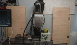
Another BF-30MVL CNC Conversion
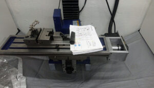
The victim a HBM BF-30MVL bench top vertical mill.
The HBM BF-30MVL variant was chosen because of its 30 Taper spindle that I prefer over the R8 ot MT3 that most other variations are equiped with.
Updated: DEC 18 2023 and alive. Note: some downloadable files at the bottom of this page.
-Timing belts and Ballscrews-
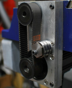
I want a build that are space saving so thats why I chose belt driven ballscrews, a nice things with belts is that I also easy can change the gearing if I find needs or performance benefits to do so.
And even if you want direct coupled steppers or servos you still need some couplers that can even out the imperfections in the motor to screw coupling, this might be a bellows mebrane or oldham coupling, non of those are perfect nither is the belt drive coupling that I have chosen we all have to take a decission here and I have made mine and do not judge anyone that may chose other ways :D-AC servos-
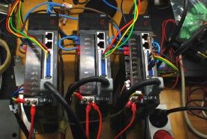
From China, today chinese made and branded AC servos are in the same price group as closed loop steppersmotors today so I went for servos they are covinient since they do not require aditional power supply to run (I know that is also true with some stepper drivers). I have chosen some servos and drives that are nopt realy well documented yet, I have still manged too get them to act pretty much the way I want them to do, some info will be posted downwards this blog and will be updated as I find some new features an/or configurations that might improve the functions I need.
-Controller board and software-early in my planning stage decided to go for LinuxCNC that is part from a great software under constant development also suported by a friendly and helpfull group of people in the LinuxCNC Forum.
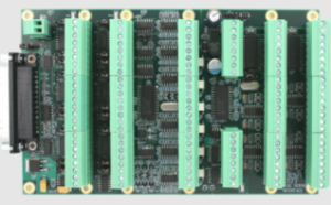
I first started out with an old PC with parallel port and a cheap breakeout board from the same country that I got my servos from but as soon as I found the great LinuxCNC compatible range of MESA Ethernet controller boards I was sold, they are not exactly cheap but not either expensive more like worth it.-My pile of parts and software-
- LinuxCNC 2.9.1: (Will change this when apropriate and also make notes if config need changes).
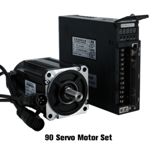
- Servo motors: For XYZ: 90ST-M02430 and A1-SVD 15 Servo drivers
- Ball screws: DFU2005 for XY and DFU 2505 for Z
- Belt drives: For motor to ballscrew coupling XY 30T-30T HDT5M-25
- Belt drive: For motor to ball screw coupling and reduction on Z 30T-60T HDT5M-25
- PC: Old HP G3 Mini Core i5 mini PC + MESA 7i76e
- Miscellaneous tuff: Some NC PNP prox sensors and other small electric and electronic parts (Might mention them later).
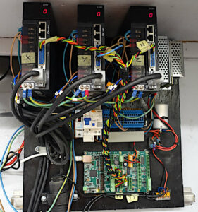
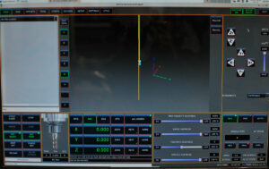
I have completed the motor/ballscrew installation on my X-Y and Z-axis and have also got the MESA card to talk to the chinese servo drives, this is looking promising.
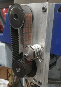
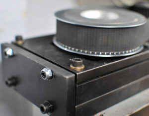
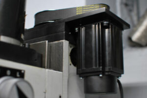
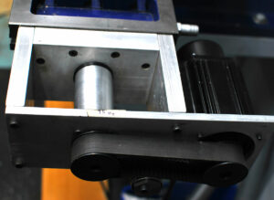
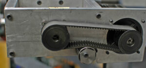
I decided to use belt transmission for AC servo to ball screw coupling to make my build more compact (having a limited space in my micro workshop).
This i how the Y-axis looks the X-axis is very similar but the Z-axis is geared down 2:1 to give it some more tourqe to lift the head. 25mm wide 5M belts are used for minimum backlash (close to zero). will post some more images later.3D Printed Homing/Limit switch holders
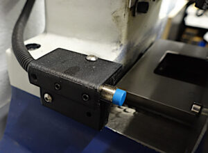
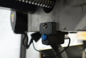
As you might know 3D printed CNC machines like PrintCNC have proven to actually work, however in this project I have choosen to use 3D printed parts only in parts that will live a life without mechanical stress.
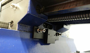
Easy to adjust proximity sensor mount is such a part Printed in ASA-CF with M5 grub screws to lock the sensor in to possition and holders themselves attached to the machine with machine screws and double sided mounting tape (I´m satis with X-axis but will redesign Z and Y).
The Spindle
I will not leave any kind of comments or thoughts about the stock DC motor spindle that I got with the spindle at delivery and are still using (15 Dec 2024) I move on to the upcoming AC servo spindle drive instead.
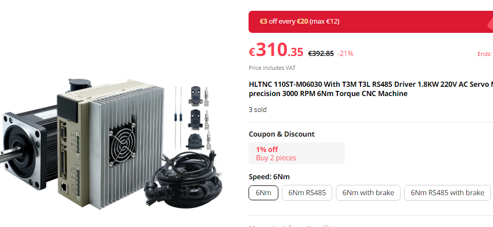
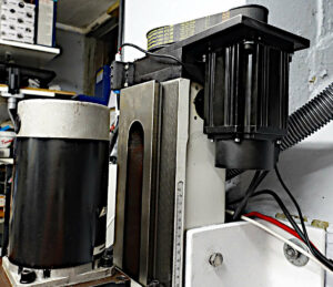
I have just recently received a 1.8KW 3000rpm China AC Servo motor and driver that I plan to get to work and serve as a Spindle motor on this mill, my plan is to have a manually switchable (by belt moving) dual spindle speed range of 0-3000 rpm and 0-6000 rpm range where the first gear obviously will have more tourqe.At the moment I have got this “spindle” motor to behave kind of nice with speed and direction controll on LinuxCNC 2.9.1 in step/dir mode together with the QT Dragon UI…. more to follow, might post ini and hal files when I’m confident haha ….
I have still not made any mounts and pulleys to be able to put this servo in to use as a spindle motor so I actually don’t know how it will work in reality but… verdict will follow.-Right now I have made some progress in my cnc conversion project. the following steps are done-
- Ball screws installed (Dual nut screws).
- Base cut to extend Y-travel with about 50mm
- AC servo motors installed and tuned.
- Limit/homing switches istalled and rigged.
- Controll box is up and running but need some finnishing work and a cover.
- Tramming done.
-In the piplane to do-
- Fabricate and install a milling head spacer for better Y-axis work space for vices.
- AC Servo spindle motor with belt drive to be contructed and installed (1.8KW AC servo motor and drive on order, multi rib belts will be turned in house.
- Pneumatic actuated power drawbar with spring washers (will use threaded draw bar).
- AC servo motor and the pneumatic power drawbar might tempt me to try a new ATC concept ;)
- Tidy up installation and make some covers for the belt drives and servo motors.
- Chip controll and mist lube/cooling.
- Tool setter to be installed.
- 3D probe to be installed.
- Covers and chip controll solution not yet designed.
-Movie playlist-
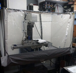
First: Homing sequence, 2nd Surfacing simulation, 3rd Compact fold away CNC enclosure
-Image galleries-
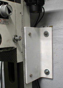
Some comments on first gallery: The brazes (white angle iron on the sides of the Z-axis colkumn) to the wall behind is a greate improvement of the stabiliy of this mill, I use oversized holes in all possitions to allow for clamping the collumn without implement any distorsion in the structure, the goole is to controll vibration the angle profile is 180x90x10mm and expandtion and column bolts are M10.
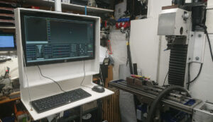
The 2nd image slider shows my compact living foldable CNC cabinet for chip control.
-Links and downloads-
English translation of Chinese A1-SVD Series Servo drivers user manual
894 DownloadsMy LinuxCNC config files for the HBM BF-30MVL “not really stock”.
256 Downloads-Aditional notes and comments-
According the A1-SVD 15 drives, I currently use the following settings including and part from delivery stock.
- Fn009 – 230 (Supply Voltage).
- Pn001 – Motor type (Check motor manual) I use “7” for my 750W AC servo motor.
- Pn002 – 2 (Step/Dir mode)
- Pn003 – 1 (Motor enable) enabled at power up.
- Pn098 – Encoder gearing, i use 5 for X and Y and 10 for Z since I use belt gearing 2:1 for Z And 1:1 for XY.
If you find something strange in those settings or my LinuxCNC config I would love to hear from you!
January 14, 2023
3D printer hardware test board build
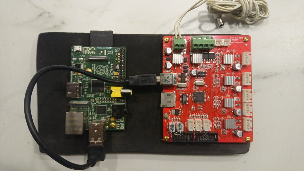
This writeup is about how to use Klipper firmware on an old abandoned 3D printer mainboard to use as a test rig for 3D printer hardware.
That was one of the longest headers that I have been written :o)
Klipper firmware can be installed on a large range of 3D printer main boards both low and high end devices. The Klipper host and UI can be installed on any Linux device with a few options of UI to use.
It can be hosted on Windows and MacOS but then you are limited to OctoPrint UI*What hardware and software did I chose and why.
- Klipper firmware since it is easy to tweak and change hardware config simply by edit a single text file.
- Fluidd User interface because it has a modest demand on the host hardware it can actually run ok on a Pi Zero first gen or a Pi of the verry first editions it also have a nice looking UI with lots of config options however not as extensive as OctoPrint but I like it clean
- ANY Board that might be close to the trash bin or in the recycle bin that fits the task and there are many at Github you can find those that already have a prebuilt config but it is definitely possible to get most boards with compatible MCU to work.
- Why? I wanted to be able to test new hardware like extruders and complete print heads of the printer before installation. Also I can use the bord to heat up a clogged hotend for cleanup, no oven no heat gun needed!
- Write up purpose Well it isn’t quite as straight forward as you think to fool Klipper to work with a lot of hardware and sensors absent so I will let you know how to cheat ;)
*Att least least time I checked.
Installing Klipper host on any Linux machine Raspberry pi or other
- This is the easy part if you prefer easy, look elsewhere if you fell to be “advanced”.
Install Linux/Rasperry OS or whatever Linux you feel for.- Visit Kiauh at github and follow the easy instruction to install Klipper, Mooraker and Fluidd just install Fluid, Moonraker and Klipper (Or chose any other config and “you are on your own ;) ” https://github.com/th33xitus/kiauh.
https://www.obico.io/blog/install-klipper-with-fluidd-ender-3/- Install firmware on your old “but newborn 3D hardware testing motherboard” 3D printer
motherboard. If you prefer video this is someone else tutorial or you can get a ready made iso here Fluid Klipper ISO- Surf to the ip your klipper install was installed at, if you cant find it look in your router config or get the excellent Fing app 4 free to check your connected network devices for IP!
Configuring Klipper/Fluidd as a test rig
This is was this post is all about, geting klipper/Fluidd to run is covered by many other websites and bloggs so lets get on with what you are here for :D
Now when you have Klipper running and are able to connect to the host lets get in to the configuration.
Here is where you figure out that Klipper are quite safe in basic configuration, it will not allow many deviations from an expected 3D printer config.So in my case when I wanted to test my newly designed The OXtruder I had difficulties to run the extruder only because Klipper expected that I had….
- Homed the printer
- Heated the “hotend”
- Heated the “bed”
- ……
How to cheat Klipper
Homing the printer without homing the printer insert or edit this [force_move] in to printer.cfg in klipper menu (http://xxxxxx.x.x/#/configure)
[heater_bed]
heater_pin: PD4
sensor_type: EPCOS 100K B57560G104F
sensor_pin: PA6
min_temp: -273.15
max_temp: 200[extruder]
step_pin: PB1
dir_pin: PB0
enable_pin: !PD6
rotation_distance: 34.095
microsteps: 16
gear_ratio: 5:1 # Orbiter gear ratio
nozzle_diameter: 0.400
filament_diameter: 1.750
heater_pin: PD5
sensor_type: EPCOS 100K B57560G104F
sensor_pin: PA7
min_temp: 0.0
max_temp: 240
max_extrude_only_distance: 500.0
min_extrude_temp: 0.0[force_move]
enable_force_move: true
# Set to true to enable FORCE_MOVE and SET_KINEMATIC_POSITION
# extended G-Code commands. The default is false.Complete Tronxy x5sa CXY-V.2-0508 Config file
File above will most likely get you going to produce a lab board with virtually any 3D printer main board.
I have done the same with an old Ender 3 Pro board (Pre silent board I may upload config for this board later).Faking heater sensors
The easy way is to jumper the heater sensor pins “sensor_type” and “sensor_pin: PA7” is your targets) on the board with appropriate resistors.
If you chose to have the same sensors as named in the config as in my example you will be fine with 18-20K for extruder and 10-14K for heated bed, check image.
EPCOS 100K B57560G104F Data sheetNOTE: Values above may be dependent on you board/sensors/steppers/gearing e.t.c
Contact me if you get lost but not until you have hit the wall ;)
Proof of working riggs.
Water cooled hot end prototype (sorry for the flickering LED lights I’m kind of a rookie on video, I will try to better) .
Worpress posts ends here!
How to include Wordpress posts in a static HTML page
(Or how I did at least!)
(Or how I did at least!)
This is the how to.
1.
I created a php file that i call ok.php (You can name it whatever)
This php file now rests in the same directory as my .html file and
contains this code:***************************************************
<?php
$args = array( 'numberposts' => 6,
'post_status'=>"publish",'post_type'=>"post",'orderby'=>"post_date");
$postslist = get_posts( $args );
foreach ($postslist as $post) : setup_postdata($post); ?>
<div class="events">
<p><strong><?php the_date(); ?></strong></p>
<p><a href="<?php the_permalink(); ?>" title="<?php the_title(); ?>"><?php the_title(); ?
><?php the_content(); ?></a></p>
</div>
<?php endforeach; ?>
*******************************************************
[GET THE CODE HERE opens in new window as pure text]
2.
In the html code between body tags i put this where I want the posts to show.******************************************
<!--#include virtual="ok.php" -->
******************************************
[GET THE CODE HERE opens in new window as pure text]
That was the way I did it and the result can be found on
the top of this page HERE!
OK
OK2
Free hosting & domain name. 1000MB and .com or .co.uk domain free for 1 year.
Limited time only. Check www.one.com for more details
