PCB UV exposure box from flatbed scanner

Disclaimer not yet officially published and will be updated frequently!
I wanted to be able to make my own prototype PCB’s and was consider many different methods.
My conclution is that part from the not so nice to handle liquids that is nessesary to use the photoresist and etching method is by far the best and fastest for a home shop. This is tep one in a small series that will cover the tools and methods that I have ben choosen. Hopefully I will also build a PCB drilling CNC ;)

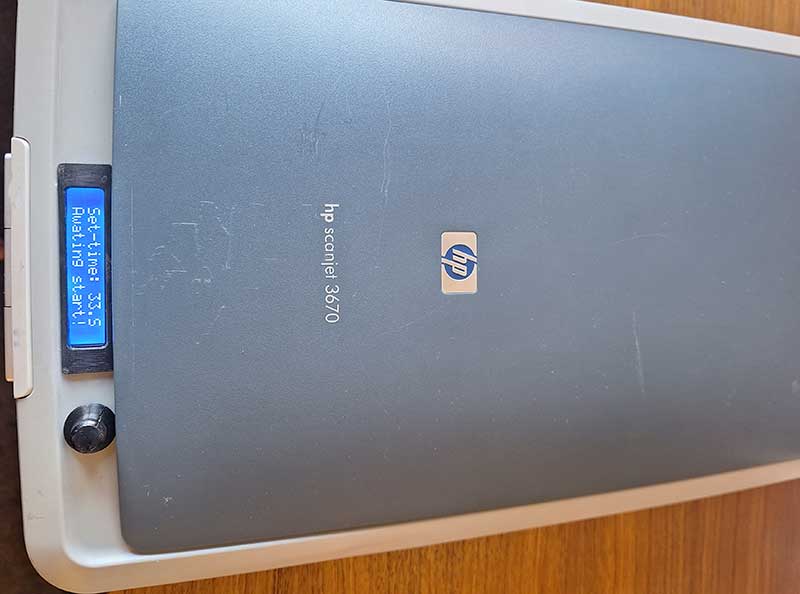
The victim to become transformation to UV exposure box a HP Scanjet 3670 bought for 20 euro’s.
It has been striped for all its internals I just keept the frot push buttons and two of them are used for start/stop of timer. It hade a space at the front top where I was able to cut a hole ad squeeze in the LCD.
I 3D printed a bezel for the LCD as my cutting wasn’t to pretty , and the potento meter knob was also printed files included att the bottom ;)Diffusion film att the bottom of the glass
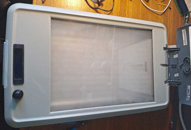
A pic showing the diffusion film being taped under side of and arround the edges of the scanner glass 
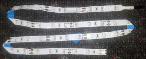
surface. The LED strip was first mounted on a white cardboard that was mounted with hot glue to the botom of the emty scanner casing. I was cutting the whole 5 meter UV light strip in short lengths and then soldered jumper wites between them. Later I found a much better and easier method, simply folding the strip!

Hardware and build for PCB UV exposure box.

Old flatbed scanner (Pick one with enough space for LCD, PCB boards and Potentiometer BOM below.


BOM: LED+BOX MOD
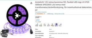
UV Led strip 5 meter.

White hard or cardboard.
Diffusion gel film.


The timer circuit and code.

No flickering solution is based on this code: devxplained.eu/en/blog/using-lcds
Timer code partly borrowed from: robojax.com
Schematics also by robojax.com my PCB does however carry all components exept LCD potentometer and buttons this will make it more easy to place the parts inside the scanner itself ther for I also used a Arduino Nano instead of UNO . 
UV exposur timer schematic

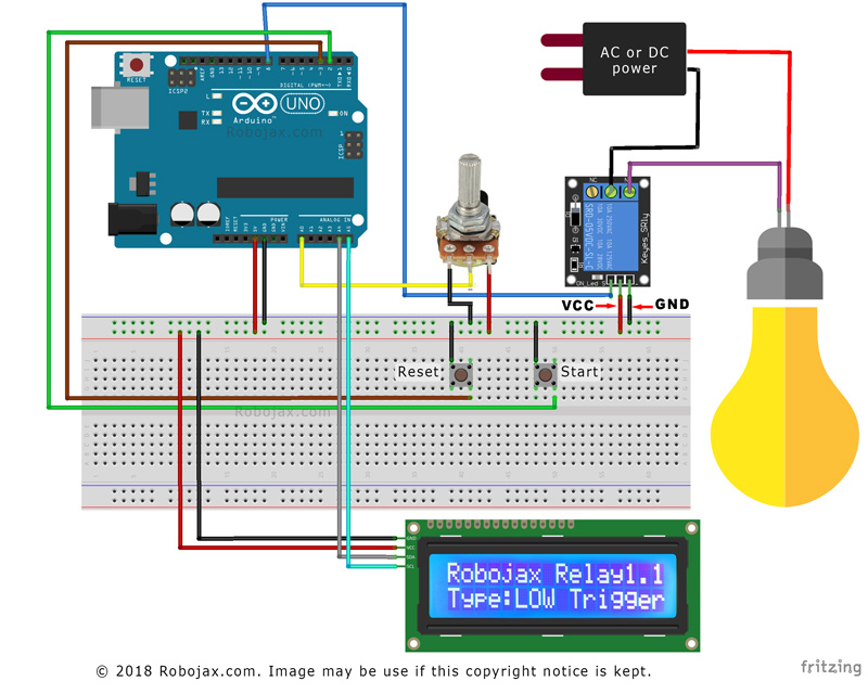
Schematic fritzing style!

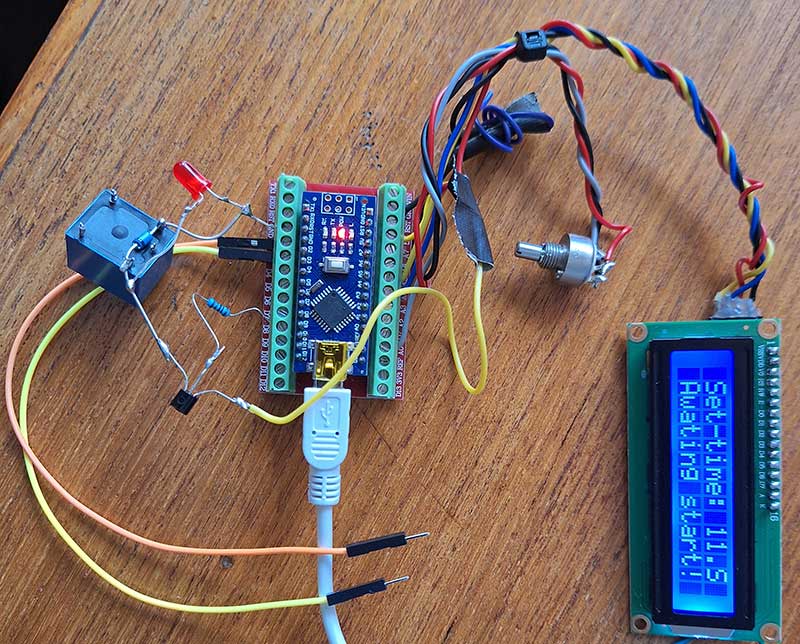
And my rats nest for testing. The UV box that I’m using right now has this circuit and is point to point wired with soldered jumpers, everything held in place by some fancy hot glue haha….
Display and arduino +relay is also powered with the same 12V power supply that are used for the UV led strips by the use of a 12v-5v DC-DC buck converter.


The full code for UV exposure timer used in Arduino IDE  (zip download near bottom of this page)


//By tinker site https://stockholmviews.com
//Most of the code “by https://robojax.com/” A few modifications to suite my needs for a PCB UV exposure board.
//I also finally managed to get the i2c display code to become flicker free.. eureka!  ;)

// start of settings for HD44780 with I2C
#include <Arduino.h>
#include <LiquidCrystal_I2C.h>
#include <IoAbstractionWire.h>
#include<Wire.h>
// Set the LCD address to 0x27 for a 16 chars and 2 line display
LiquidCrystal_I2C lcd(0x27, 16, 2);

#define relayPin 8 // the pin relay is connected
#define potPin  A0 // the pin potentiometer is connected
#define resetPin 3 // the pin where rest switch is connected
#define startPin 2 // the pin where start switch is connected

#define relayType ‘L’ // Relay trigger type. L for low and H for high
const int maxTime = 200;// maximum timer time in seconds 2 minutes is more than enough for my PCB UV box
const int minTime = 2; // miniimum timer time in seconds

// do not change anything bellow here
long duration;// holds the duration of timer
int potValue;// holds the variable resistor (potentiometer) value
long rememTime;// holds current run time
int relayState =0;// holds relay state

void setup() {

  lcd.begin(16, 2);
  lcd.backlight();
  lcdDisplay(0, “Set-time:”, ” ” , “.S” );
  lcdDisplay(1, “Awating start! “, 0, ” “);

  Wire.begin();
   
  pinMode(relayPin, OUTPUT);
  pinMode(resetPin, INPUT_PULLUP);
  pinMode(startPin, INPUT_PULLUP);
  attachInterrupt(digitalPinToInterrupt(resetPin), reset, LOW);

  Serial.begin(115200);// initialize serial monitor with 9600 or your choice of baud rate.
  if(relayType == ‘H’) // H or L depending on activted LOW or activeted HIGH by pin 8.
  {
    digitalWrite(relayPin, HIGH);// turn the relay OFF and keep it OFF.  
      Serial.println(“Countdown relay”);
      Serial.println(“Type:LOW Trigger”);      
  }else{
    digitalWrite(relayPin, LOW);// turn the relay OFF and keep it OFF.
      Serial.println(“Countdown relay”);
      Serial.println(“Type:HIGH Trigger”);  
  }
  delay(0);
}

void loop() {
      potValue = analogRead(potPin)/10;// reads the value of the potentiometer I use 10K multi turn pot (value between 0 and 1023).

    int durationCalc = map(potValue, 0, 102, minTime, maxTime);// convert A0 value to time set minTime and maxTime.
   
    if(digitalRead(startPin) ==LOW)
    {
     duration = durationCalc;
     rememTime = millis()/1000;
     relayState = 1;
     controlRelay();// turns the relay ON
           
    }
   if(  ( millis()/1000- rememTime) > duration )
   {
    relayState = 0;// change relay state to OFF
    controlRelay();// control relay with new relay state
   
   }
      Serial.print(“Time set: “);
      Serial.print(duration);
      Serial.print (” S “);  
 
           
    if(relayState ==1){  

      lcd.noBlink();
      lcdDisplay(0, “Run-time: “, duration, “.S”);
      lcdDisplay(1, “Exposing: “, getRtime(), “.S “);        
      Serial.print(” remain: “);
      Serial.print(getRtime());//
      Serial.print(” .S”);  
    }else{
      lcd.noBlink();
      lcdDisplay(0, “Set-time: “, durationCalc,  “.S”);
      lcdDisplay(1, “Awating start! “, 0, “”);        
    }
    Serial.println();  
         
 delay(50); // wait for 200 milliseconds      
}// loop end

 void controlRelay()
 {
 
  if(relayType == ‘L’)
  {
     if(relayState == 1)
     {
    digitalWrite(relayPin, LOW);// turns Low-Trigger relay ON
      Serial.print(“LT-Relay ON for “);
      Serial.print(duration);// display in seconds
      Serial.println(” Seconds”);
     }else{
    digitalWrite(relayPin, HIGH); // turns Low-Trigger relay OFF
      Serial.println(“====Relay is OFF”);
     }
     
  }else{
   
     if(relayState == 1)
     {    
      digitalWrite(relayPin, HIGH);// turns High-Trigger relay ON
      Serial.print(“HT-Relay ON for “);
      Serial.print(duration);// display in seconds
      Serial.println(” Seconds”);  
     }else{
      digitalWrite(relayPin, LOW); // turns High-Trigger relay OFF
      Serial.println(“==Relay OFF”);  
     }  
  }

}//controlRelay end


void reset()
{
 
  duration =0;
   if(relayType == ‘L’)
  {
    digitalWrite(relayPin, HIGH);// turn OFF High trigger relay    
  }else{
    digitalWrite(relayPin, LOW);// turn OFF Low trigger relay
 
  }
  Serial.println(“Relay OFF”);

}//reset()


int getRtime()
{
  return duration – (millis()/1000- rememTime);
}

void lcdDisplay(int rowNum, String titleText, int valueText, String value2Text)
{
    clearRow(rowNum);

    String myStr;
    myStr = String(valueText);

    int titleTextLength = titleText.length();

   lcd.setCursor (0,rowNum); //
   lcd.print(titleText);
   
   lcd.setCursor (titleTextLength,rowNum); //
   lcd.print(myStr);
   
   lcd.setCursor (myStr.length()+titleTextLength,rowNum); //
   lcd.print(value2Text);  
}
void clearRow(int r)
{
  //
  for(int i=0; i<16; i++)
  {
   lcd.setCursor (i,r); //
   if(relayPin, LOW) lcd.print(” “);
  }
}//clearRow end


Notes

If you don’t have a multi turn potentiometer on hand but still like fine controll of time settings, you can use two potentiometers in series like in the original set up se more here: robojax.com relay_timer_1.1

Files to download (to be added)

1 Download

stl’s for bezel an knob + box for freestanding timer.
PCB files
More images